|
|
|
|
 |
Click
here for a full cut sheet
|
|
Features and Benefits:
|
The 384 series Alloy-C ball valve incorporates several innovative design features for improved process performance. The dual pattern ISO 5211 mounting pad facilitates direct mounting of pneumatic and electric actuators. In combination with our high-cycle, live-loaded stem packing system, the 384 series ball valve provides an ideal choice for all your automation requirements. |
|
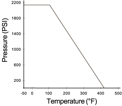
Operating / Test Conditions:
|
|
|
Options:
|
Materials List
|
Item
|
Part
Name
|
Material
|
Qty
|
|
1
|
Body
|
CW12MW
(Alloy-C)
|
1
|
|
2
|
End
Cap
|
CW12MW
(Alloy-C)
|
2
|
|
3
|
Body
Seal
|
TFM
|
2
|
|
4
|
Ball
|
CW12MW
(Alloy-C)
|
1
|
|
5
|
Seat
|
TFM
|
2
|
|
6
|
Body
Bolt
|
304SS
|
4/6**
|
|
7*
|
Thrust
Washer
|
PEEK
|
1
|
|
8
|
Stem
|
CW12MW
(Alloy-C)
|
1
|
|
8A*
|
Half
Split Ring
|
CW12MW
(Alloy-C)
|
1
|
|
9
|
Stem
Packing Set
|
TFM
|
1
|
|
10
|
Gland
Washer
|
304SS
|
1
|
|
11
|
Belleville
Washer
|
301SS
|
4
|
|
12
|
Gland
Nut
|
304SS
|
1
|
|
13
|
Gland
Nut Lock Washer
|
304SS
|
1
|
|
14
|
Stem
Spacer
|
304SS
|
1
|
|
15
|
Plater
|
304SS
|
1
|
|
16
|
Stop
Pin
|
304SS
|
1
|
|
17
|
Handle
Nut
|
304SS
|
1
|
|
18
|
Handle
|
304SS
|
1
|
|
19
|
Handle
Cover
|
Vinyl
|
1
|
|
20**
|
Set
Bolt
|
304SS
|
1
|
|
21**
|
Lever
Head
|
CF8
|
1
|
|
22**
|
Lever
|
Steel
Pipe
|
1
|
|
23
|
O-Ring
|
Viton
|
1
|
*1/4" - 1/2"
(Full Port)
1/2" - 3/4" (Standard Port)
**2" (Full Port)
2-1/2" (Standard Port)
DIMENSIONS (Inches)
|
Size
|
A
|
B | C | D | E | F | G |
H
|
K | L | ISO 5211 Pattern |
Wt.
(lbs)
|
|
| 384F | 384S | ||||||||||||
|
1/4
|
---
|
1.81
|
0.35
|
5.11
|
0.43
|
1.41
|
1.65
|
0.23
|
0.23
|
0.35
|
2.63
|
F03/F04*
|
1.75
|
|
3/8
|
---
|
1.81
|
0.35
|
5.11
|
0.49
|
1.41
|
1.65
|
0.23
|
0.23
|
0.35
|
2.63
|
F03/F04*
|
1.75
|
| --- | 1/2 |
1.81
|
0.35
|
5.11
|
0.49
|
1.41
|
1.65
|
0.23
|
0.23
|
0.35
|
2.67
|
F03/F04*
|
1.75
|
|
1/2
|
3/4
|
1.73
|
0.35
|
5.11
|
0.59
|
1.41
|
1.65
|
0.23
|
0.23
|
0.35
|
3.37
|
F04/F05*
|
2.45
|
|
3/4
|
1
|
1.88
|
0.47
|
6.10
|
0.78
|
1.65
|
1.96
|
0.23
|
0.23
|
0.43
|
3.77
|
F04/F05*
|
4.40
|
|
1
|
1
1/4
|
2.08
|
0.47
|
6.10
|
0.98
|
1.65
|
1.96
|
0.23
|
0.27
|
0.43
|
4.21
|
F05/F07*
|
6.05
|
|
1
1/4
|
1
1/2
|
2.36
|
0.61
|
8.07
|
1.25
|
1.96
|
2.75
|
0.27
|
0.36
|
0.55
|
4.37
|
F05/F07*
|
7.40
|
|
1
1/2
|
2
|
2.75
|
0.61
|
8.07
|
1.49
|
1.96
|
2.75
|
0.27
|
0.36
|
0.55
|
5.07
|
F07/F10*
|
11.35
|
|
2
|
2
1/2
|
3.42
|
0.82
|
11.81
|
1.96
|
2.75
|
4.01
|
0.36
|
0.44
|
0.66
|
6.10
|
F07/F10*
|
23.30
|
*Direct mount with stem adapter bushing
Due to continuous product development, information may change without notice.