|
|
|
|
 |
Click
here for a full cut sheet
|
|
Features and Benefits:
|
The 364 series diverter valve incorporates several innovative design features for improved process performance. This standard or full-port diverter valve is available in side or bottom porting. The 3-piece design yields enhanced performance at a cost saving. The ISO 5211 mounting pad allows for Direct Mounting of most actuators. |
|
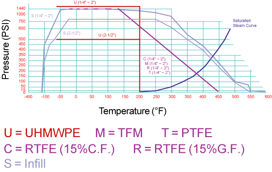
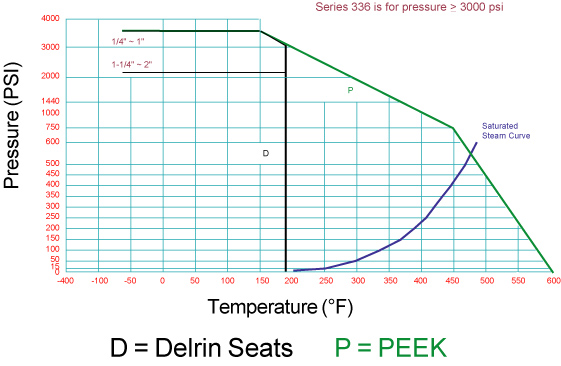
Operating / Test Conditions:
|
|
|
Options:
|
Materials List
|
Item
|
Part
Name
|
Material
|
Qty
|
|
1
|
Body
|
A351
Gr. CF8M
|
1
|
|
2
|
End
Cap
|
A351
Gr. CF8M
|
3
|
|
3
|
Ball
|
A351
Gr. CF8M
|
1
|
|
4
|
Stem*
|
316SS
17-4 |
1
|
|
5
|
Seat
|
TFM
|
2
|
|
6
|
Body
Seal
|
TFM
|
3
|
|
7
|
Body
Bolt
|
304SS
|
8
|
|
8
|
Body
Nut
|
304SS
|
8
|
|
9
|
Thrust
Washer
|
PEEK
|
1
|
|
10
|
Stem
O-Ring
|
Viton
90
|
1
|
|
11
|
Stem
Packing Set
|
TFM
|
1
|
|
12
|
Packing
Gland
|
304SS
|
1
|
|
13
|
Belleville
Washer
|
301SS
|
4
|
|
14
|
Gland
Nut
|
304SS
|
1
|
|
15
|
Gland
Nut Lock Washer
|
304SS
|
1
|
|
16
|
Stem
Spacer
|
304SS
|
1
|
|
17
|
Stop
Pin
|
304SS
|
1
|
|
18
|
Stop
Pin Washer
|
301SS
|
1
|
|
19
|
Stop
Pin Nut
|
304SS
|
1
|
|
20
|
Handle
|
304SS
|
1
|
|
21
|
Handle
Nut
|
304SS
|
1
|
|
22
|
Handle
Nut Lock Washer
|
304SS
|
1
|
|
23
|
Handle
Cover
|
Vinyl
|
1
|
|
24
|
Stem
Set Pin
|
316SS
|
1
|
* For Delrin or PEEK seats, the valve stem will be changed to 17-4
DIMENSIONS (Inches)
|
Size
|
L
|
M
|
P | H | H1 | H2 | H3 | D1 |
D2
|
d1 | d2 | S | ISO 5211 Pattern |
Wt.
(lbs)
|
|
| 364F | 364S | ||||||||||||||
|
1/4
|
---
|
2.57
|
5.41
|
0.44
|
3.02
|
1.80
|
0.38
|
2.49
|
1.97
|
1.42
|
0.26
|
0.24
|
0.35
|
F03/F05*
|
2.19
|
|
3/8
|
1/2
|
2.57
|
5.41
|
0.44
|
3.02
|
1.80
|
0.38
|
2.49
|
1.97
|
1.42
|
0.26
|
0.24
|
0.35
|
F03/F05*
|
2.21
|
|
1/2
|
3/4
|
2.80
|
5.41
|
0.57
|
3.11
|
1.89
|
0.38
|
2.69
|
1.97
|
1.42
|
0.26
|
0.24
|
0.35
|
F03/F05*
|
2.87
|
|
3/4
|
1
|
3.69
|
6.37
|
0.81
|
3.21
|
1.99
|
0.43
|
3.43
|
1.97
|
1.65
|
0.26
|
0.24
|
0.43
|
F04/F05*
|
4.95
|
|
1
|
1
1/4
|
4.19
|
6.37
|
1.00
|
3.41
|
2.19
|
0.44
|
3.88
|
1.97
|
1.65
|
0.26
|
0.24
|
0.43
|
F04/F05*
|
7.27
|
|
1
1/4
|
1
1/2
|
4.54
|
8.02
|
1.25
|
4.24
|
2.56
|
0.61
|
4.39
|
2.76
|
1.97
|
0.35
|
0.27
|
0.55
|
F05/F07*
|
11.39
|
|
1
1/2
|
2
|
4.98
|
8.02
|
1.50
|
4.52
|
2.83
|
0.61
|
4.83
|
2.76
|
1.97
|
0.35
|
0.27
|
0.55
|
F05/F07*
|
14.99
|
|
2
|
2
1/2
|
5.87
|
5.51
|
2.00
|
5.44
|
3.50
|
0.77
|
5.71
|
4.02
|
2.76
|
0.44
|
0.35
|
0.67
|
F07/F10*
|
30.12
|
*Direct mount with stem adapter bushing
Due to continuous product development, information may change without notice.