|
|
|
|
|
Features and Benefits:
|
The 337F series ball valve incorporates several innovative design features for improved performance. The valve's uniform bore diameter improves flow characteristics and eliminates pooling of potential contaminants. Roll burnishing and polishing all 316L stainless steel internal surfaces reduces surface porosity and improves finish. The ISO 5211 mounting pad allows for direct mounting of most actuators. |
|
Operating / Test Conditions:
|
|
|
Options:
|
(TFM
Seats)
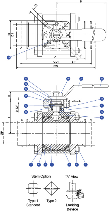
*Valve with Cavity Filled Seats Shown*
Materials List
|
Item
|
Part
Name
|
Material
|
Qty
|
|
1
|
Body
|
A351
Gr. CF3M
|
1
|
|
2
|
End
Cap
|
A351
Gr. CF3M
|
2
|
|
3
|
Ball
|
316L
SS
|
1
|
|
4
|
Stem
|
316L
SS
|
1
|
|
5
|
Seat
|
TFM
|
2
|
|
6
|
Body
Seal
|
TFM
|
2
|
|
7
|
Body
Bolt
|
304SS
|
4*
|
|
8
|
Body
Nut
|
304SS
|
4*
|
|
9
|
Thrust
Washer
|
PEEK
|
1
|
|
10
|
Stem
O-Ring
|
Viton
90
|
1
|
|
11
|
Stem
Packing Set
|
TFM
|
1
|
|
12
|
Packing
Gland
|
304SS
|
1
|
|
13
|
Belleville
Washer
|
301SS
|
4
|
|
14
|
Gland
Nut
|
304SS
|
1
|
|
15
|
Gland
Nut Lock Washer
|
304SS
|
1
|
|
16
|
Stem
Spacer
|
304SS
|
1
|
|
17
|
Stop
Plate
|
304SS
|
1**
|
|
18
|
Positioning
Pin
|
304SS
|
1
|
|
19
|
Handle
|
304SS
|
1
|
|
20
|
Handle
Nut
|
304SS
|
1
|
|
21
|
Handle
Cover
|
Vinyl
|
1
|
*6 Nuts and Bolts on
4" Valve
** 2-1/2",
3", and 4" only
DIMENSIONS (Inches)
|
Size
|
CL
|
CL1
|
EW
|
P
|
M
|
H
|
h
|
D1
|
d1
|
D2
|
d2 |
S
|
ISO
5211 Pattern
|
Weight
(lbs)
|
|
1/2
|
3.50
|
-
|
4.90
|
0.37
|
4.92
|
1.54
|
0.35
|
1.42
|
0.22
|
1.65
|
0.22
|
0.35
|
F03/F04*
|
1.60
|
|
3/4
|
3.50
|
4.00
|
5.60
|
0.62
|
4.92
|
1.54
|
0.35
|
1.42
|
0.22
|
1.65
|
0.22
|
0.35
|
F03/F04*
|
1.60
|
|
1
|
3.50
|
4.50
|
6.40
|
0.87
|
5.91
|
1.89
|
0.51
|
1.65
|
0.22
|
1.97
|
0.27
|
0.43
|
F04/F05*
|
3.06
|
|
1
1/2
|
4.50
|
5.50
|
7.20
|
1.37
|
7.87
|
2.36
|
0.63
|
1.97
|
0.28
|
2.76
|
0.35
|
0.55
|
F05/F07*
|
5.76
|
|
2
|
5.00
|
6.25
|
7.60
|
1.87
|
7.87
|
2.74
|
0.63
|
1.97
|
0.28
|
2.76
|
0.35
|
0.55
|
F05/F07*
|
8.63
|
|
2
1/2
|
6.75
|
-
|
10.00
|
2.37
|
11.61
|
3.50
|
0.79
|
2.76
|
0.35
|
4.02
|
0.44
|
0.67
|
F07/F10*
|
18.85
|
|
3
|
7.75
|
-
|
11.00
|
2.87
|
11.61
|
3.86
|
0.79
|
2.76
|
0.35
|
4.02
|
0.44
|
0.67
|
F07/F10*
|
29.61
|
|
4
|
9.50
|
-
|
12.00
|
3.83
|
13.39
|
5.16
|
0.98
|
4.02
|
0.44
|
4.92
|
0.53
|
0.87
|
F10/F12*
|
53.27
|
*Direct mount with stem adapter bushing
Due to continuous product development, information may change without notice.