|
|
|
|
|
Click
here for a full cut sheet
|
|
|
Features and Benefits:
|
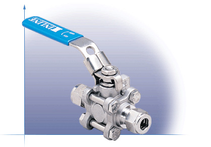
The 317C Compression Ends ball valve combines tube full port construction with a variety of sanitary end connections to deliver outstanding performance in high purity applications. The valve's uniform bore diameter and polished internal surfaces improve flow characteristics and eliminate pooling of potential contaminants. |
|
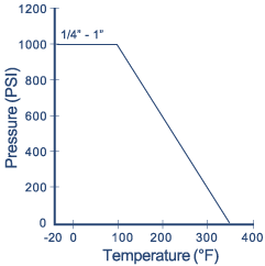
Operating / Test Conditions:
|
|
|
Options:
|
(PTFE
Seats)
![]()
Assembly and Reassemble Instruction
![]()
|
Assembly Instruction
Reassemble Instruction
|
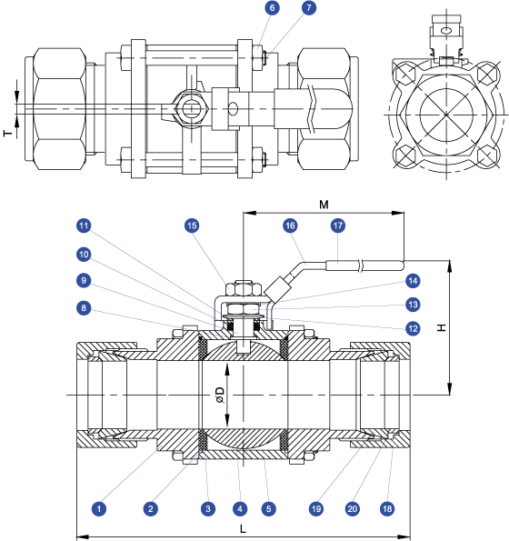
Materials List
|
Item
|
Part
Name
|
Material
|
Qty
|
|
1
|
End
Cap
|
A351
Gr. CF8M
|
2
|
|
2
|
Body
Seal
|
PTFE
|
2
|
|
3
|
Seat
|
PTFE
|
2
|
|
4
|
Ball
|
316SS
|
1
|
|
5
|
Body
|
A351
Gr. CF8M
|
1
|
|
6
|
Body
Nut
|
304SS
|
4
|
|
7
|
Body
Bolt
|
304SS
|
4
|
|
8
|
Thrust
Washer
|
PEEK
|
2
|
|
9
|
Stem
|
316SS
|
1
|
|
10
|
Stem
Packing Set
|
PTFE
|
1
|
|
11
|
Packing
Gland
|
304SS
|
1
|
|
12
|
Belleville
Washer
|
301SS
|
1
|
|
13
|
Nut
Stop
|
304SS
|
1
|
|
14
|
Gland
Nut
|
304SS
|
2
|
|
15
|
Handle
Nut
|
304SS
|
1
|
|
16
|
Handle
|
304SS
|
1
|
|
17
|
Handle
Cover
|
Vinyl
|
1
|
|
18
|
Locking Nut | 316SS | 2 |
|
19
|
Front Ferrule | 316SS | 2 |
|
20
|
Back Ferrule | 316SS | 2 |
DIMENSIONS (Inches)
|
Size
|
L
|
D
|
M
|
H
|
T
|
|
1/4
|
3.14
|
0.38
|
4.33
|
2.00
|
0.20
|
|
3/8
|
3.33
|
0.38
|
4.33
|
2.00
|
0.20
|
|
1/2
|
3.61
|
0.38
|
4.33
|
2.00
|
0.20
|
|
3/4
|
3.88
|
0.62
|
5.08
|
2.30
|
0.26
|
|
1
|
4.60
|
0.87
|
5.67
|
2.70
|
0.31
|
*Direct mount with stem adapter bushing
Due to continuous product development, information may change without notice.