|
|
|
|
|
Click
here for a full cut sheet
|
|
|
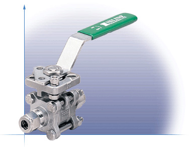
Features and Benefits:
|
The 304C Compression Ends ball valve incorporates several innovative design features for improved process performance. The uniform bore diameter improves flow rates and minimizes pressure drop through the valve. The dual pattern ISO 5211 mounting pad facilitates direct mounting of pneumatic and electric actuators. In combination with our high-cycle stem packing system, the 304F series ball valve provides an ideal choice for all your automation requirements. |
|
Operating / Test Conditions:
|
|
|
Options:
|
(RTFE
Seats)
![]()
Assembly and Reassemble Instruction
![]()
|
Assembly Instruction
Reassemble Instruction
|
Materials List
|
Item
|
Part
Name
|
Material
|
Qty
|
|
1
|
End
Cap
|
A351
Gr. CF8M
|
2
|
|
2
|
Body
Seal
|
PTFE
|
2
|
|
3
|
Seat
|
PTFE
(15% C.F.)
|
2
|
|
4
|
Ball
|
316SS
|
1
|
|
5
|
Body
|
A351
Gr. CF8M
|
1
|
|
6
|
Spring
Washer
|
304SS
|
4
|
|
7
|
Body
Nut
|
304SS
|
4
|
|
8
|
Body
Bolt
|
304SS
|
4
|
|
9
|
Thrust
Washer
|
PEEK
|
1
|
|
10
|
Stem
O-Ring
|
Viton
90
|
1
|
|
11
|
Stem
|
316SS
|
1
|
|
12
|
Stop
Pin Nut
|
304SS
|
1
|
|
13
|
Stem
Packing Set
|
PTFE
|
1
|
|
14
|
Gland
Washer
|
304SS
|
1
|
|
15
|
Belleville
Washer
|
301SS
|
2
|
|
16
|
Stem
Nut
|
304SS
|
1
|
|
17
|
Nut
Stop
|
304SS
|
1
|
|
18
|
Stop
Pin Bolt
|
304SS
|
1
|
|
19
|
Space
Washer
|
304SS
|
1
|
|
20
|
Handle
Nut
|
304SS
|
1
|
|
21
|
Handle
|
304SS
|
1
|
|
22
|
Handle
Cover
|
Vinyl
|
1
|
|
23
|
Locking
Nut
|
316SS
|
2
|
|
24
|
Front
Ferrule
|
316SS
|
2
|
|
25
|
Back
Ferrule
|
316SS
|
2
|
DIMENSIONS (Inches)
|
Size
|
L
|
C
|
D
|
D1
|
D2
|
D3
|
D4
|
d1
|
d2
|
M
|
H
|
h
|
S
|
|
1/4
|
3.33
|
2.60
|
0.43
|
0.47
|
1.65
|
1.42
|
0.99
|
0.24
|
0.24
|
5.32
|
1.46
|
0.35
|
0.36
|
|
3/8
|
3.49
|
2.60
|
0.49
|
0.47
|
1.65
|
1.42
|
0.99
|
0.24
|
0.24
|
5.32
|
1.46
|
0.35
|
0.36
|
|
1/2
|
3.76
|
2.60
|
0.59
|
0.47
|
1.65
|
1.42
|
0.99
|
0.24
|
0.24
|
5.32
|
1.46
|
0.35
|
0.36
|
|
3/4
|
4.13
|
2.60
|
0.79
|
0.47
|
1.65
|
1.42
|
0.99
|
0.24
|
0.24
|
5.32
|
1.65
|
0.37
|
0.36
|
|
1
|
4.69
|
2.60
|
0.99
|
0.55
|
1.97
|
1.65
|
1.18
|
0.28
|
0.24
|
6.30
|
1.91
|
0.43
|
0.43
|
*Direct mount with stem adapter bushing
Due to continuous product development, information may change without notice.