|
|
|
|
|
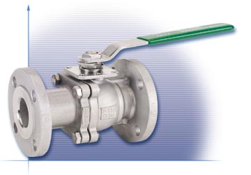
Features and Benefits:
|
Operating / Test Conditions:
|
|
Options
|
1/2" to 4"
(RTFE
Seats / Seals)
6" to 12"
(RTFE Seats / Seals)
1/2" to 4"
6" to 12"
1/2" to 4"
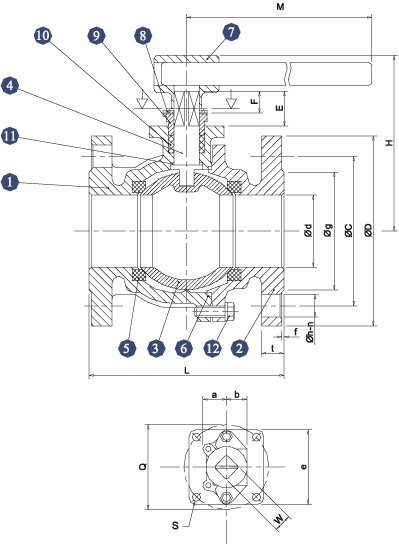
Materials List
|
Item
|
Part
Name
|
Material
|
Qty
|
|
1
|
Body
|
A351
Gr. CF8M
|
1
|
|
2
|
End
Cap
|
A351
Gr. CF8M
|
1
|
|
3
|
Ball
|
316SS
|
1
|
|
4
|
Seat
|
RTFE
(15% C.F.)
|
2
|
|
5
|
Body
Seal
|
PTFE
|
1
|
|
6
|
Bolt
& Washer
|
304SS
|
n*
|
|
7
|
Thrust
Washer
|
PEEK
|
1
|
|
8
|
Stem
Packing Set
|
PTFE
|
1
|
|
9
|
Packing
Gland
|
304SS
|
1
|
|
10
|
Stem
|
316SS
|
1
|
|
11
|
Belleville
Washer
|
301SS
|
2
|
|
12
|
Stop
Plate
|
304SS
|
1
|
|
13
|
Gland
Nut
|
304SS
|
1
|
|
14
|
Gland
Nut Lock Washer
|
304SS
|
1
|
|
15
|
Positioning
Pin
|
304SS
|
1
|
|
16
|
Handle
Nut
|
304SS
|
1
|
|
17
|
Handle
|
304SS
|
1
|
|
18
|
Handle
Cover
|
Vinyl
|
1
|
*see table below
6" to 12"
|
Item
|
Part
Name
|
Qty
|
Material
|
Option
|
|
|
1
|
Body
|
1
|
A351 Gr. CF8M
|
A351 Gr. CF8
|
A216 Gr. WCB
|
|
2
|
End Cap
|
1
|
A351 Gr. CF8M
|
A351 Gr. CF8
|
A216 Gr. WCB
|
|
3
|
Ball
|
1
|
SS316 or
CF8M
|
SS304 or CF8
|
----
|
|
4
|
Stem
|
1
|
SS316
|
SS304
|
---- |
|
5
|
Seats
|
2
|
PTFE + 15% G.F.
|
SS304
|
---- |
|
6
|
Body Seal
|
1
|
PTFE
|
----
|
---- |
|
7
|
Handle
|
1
|
Ductile (Steel Pipe)
|
----
|
---- |
|
8
|
Stopper
|
1
|
SS304
|
----
|
Carbon
Plated Steel
|
|
9
|
Gland
|
1
|
SS304
|
----
|
---- |
|
10
|
Stem Packing Set
|
2
|
PTFE
|
----
|
---- |
|
11
|
Thrust Washer
|
1
|
PTFE
|
----
|
---- |
|
12
|
Bolt & Washer
|
10
|
SS304
|
----
|
Carbon Plated Steel |
DIMENSIONS (Inches)
1/2" to 4"
|
Size
|
A
|
F
|
P
|
H
|
M
|
E
|
W
|
Q
|
S
|
G
|
L
|
|
|
ANSI
150 |
ANSI
300 |
|||||||||||
|
1/2
|
1.00
|
0.32
|
0.59
|
2.56
|
5.51
|
0.64
|
0.26
|
1.65
|
M5
|
0.39
|
4.25
|
5.51
|
|
3/4
|
1.00
|
0.32
|
0.79
|
2.95
|
5.51
|
0.64
|
0.26
|
1.65
|
M5
|
0.39
|
4.61
|
5.98
|
|
1
|
1.15
|
0.43
|
0.98
|
3.34
|
6.69
|
0.79
|
0.38
|
1.96
|
M6
|
0.55
|
5.00
|
6.50
|
|
1
1/2
|
1.60
|
0.59
|
1.57
|
4.13
|
9.06
|
1.28
|
0.38
|
2.76
|
M8
|
0.71
|
6.50
|
7.48
|
|
2
|
1.60
|
0.59
|
1.97
|
4.53
|
9.06
|
1.28
|
0.38
|
2.76
|
M8
|
0.71
|
7.01
|
8.50
|
|
2
1/2
|
1.75
|
0.77
|
2.56
|
5.20
|
13.78
|
1.35
|
0.47
|
4.02
|
M10
|
0.79
|
7.48
|
9.49
|
|
3
|
1.75
|
0.77
|
3.15
|
5.75
|
13.78
|
1.35
|
0.47
|
4.02
|
M10
|
0.79
|
7.99
|
11.14
|
|
4
|
1.90
|
0.91
|
3.94
|
6.50
|
13.78
|
1.80
|
0.59
|
4.02
|
M10
|
0.94
|
9.02
|
12.00
|
|
End
Flange(ANSI
150)
|
End
Flange(ANSI
300)
|
Wt.
(lbs)
|
|||||||||
|
D
|
Bolt
Hole
|
t
|
D
|
Bolt
Hole
|
t
|
ANSI
150
|
ANSI
300
|
||||
|
C
|
n
|
h
|
C
|
n
|
h
|
||||||
|
3.50
|
2.38
|
4
|
0.63
|
0.44
|
3.74
|
2.62
|
4
|
0.56
|
0.56
|
4.40
|
5.80
|
|
3.96
|
2.76
|
4
|
0.63
|
0.44
|
4.61
|
3.25
|
4
|
0.63
|
0.63
|
5.50
|
8.10
|
|
4.25
|
3.13
|
4
|
0.63
|
0.44
|
4.88
|
3.50
|
4
|
0.70
|
0.70
|
6.60
|
10.0
|
|
5.00
|
3.88
|
4
|
0.63
|
0.62
|
6.14
|
4.51
|
4
|
0.81
|
0.81
|
13.40
|
19.7
|
|
5.98
|
4.74
|
4
|
0.75
|
0.76
|
6.50
|
5.50
|
8
|
0.88
|
0.88
|
16.80
|
22.3
|
|
7.01
|
5.49
|
4
|
0.75
|
0.88
|
7.48
|
5.87
|
8
|
1.00
|
1.00
|
30.80
|
42.5
|
|
7.48
|
6.00
|
4
|
0.75
|
0.94
|
8.63
|
6.61
|
8
|
1.13
|
1.13
|
35.40
|
54.9
|
|
9.02
|
7.50
|
8
|
0.75
|
0.94
|
10.00
|
7.87
|
8
|
1.25
|
1.25
|
55.00
|
81.2
|
6" to 12"
|
Size
|
a
|
b
|
e
|
W
|
d
|
H
|
M
|
L
|
Q
|
S
|
E
|
F
|
Weight (lbs) |
|
6
|
1.42
|
1.20
|
4.50
|
1.10
|
5.95
|
10.04 | 32.28 | 15.51 | 4.92 | M12 | 2.46 | 1.67 | 118.0 |
|
8
|
1.71
|
1.40
|
5.35
|
1.41
|
7.90
|
13.39 | 41.34 | 17.99 | 4.92 | M12 | 2.56 | 1.69 | 202.0 |
|
10
|
1.71
|
1.40
|
5.35
|
1.41
|
9.90
|
14.96 | 41.34 | 20.98 | 4.92 | M12 | 2.60 | 1.83 | 326.0 |
|
12
|
1.71
|
1.50
|
5.50
|
1.41
|
11.85 | 22.36 | 57.48 | 24.01 | 5.51 | M16 | 2.91 | 1.61 | ---- |
|
Size
|
End
Flange
|
||||||
|
D
|
Bolt
Hole
|
g
|
t
|
f
|
|||
|
C
|
n
|
H
|
|||||
|
6
|
10.98
|
9.51
|
8
|
0.87
|
8.50
|
1.00 | 0.06 |
|
8
|
13.50
|
11.75
|
8
|
0.87
|
10.63
|
1.13 | 0.06 |
|
10
|
15.98
|
14.25
|
12
|
0.98
|
12.76
|
1.19 | 0.06 |
|
12
|
19.02
|
17.01
|
12
|
0.98
|
15.00 | 1.25 | 0.06 |
Due to continuous product development, information may change without notice.